
|
|
II-INFORMATIK3 WS04
|
Nachdem in der vorausgehenden Vorlesung aufgezeigt wurde, wie man mit Hilfe des GNU-gdb Debuggers von der Software aus alle wichtigen Hardware-Register zu kontrollieren vermag, soll im Folgenden dieses Werkzeug dazu benutzt werden, das Zusammenspiel von Software und Hardware weiter zu untersuchen.
Diese Analyse der Hardware wird unter Voraussetzung eines konkreten Betriebssystems gemacht; in diesem Fall Linux.
Es wird aufgezeigt, wie das Betriebssystem mittels boot strapping in den Speicher geladen wird. Dann wird beleuchtet, wie das Betriebssystem den Zugriff auf die Resourcen organisiert. Dabei wird in erster Linie untersucht, wie die Addressierung von Speicher erfolgt sowie der Einsatz der diversen Register.
Innerhalb dieses Rahmens werden dann konkrete Programmbeispiele betrachtet.
(für diese Darstellung siehe ausführlicher [BOVET 2003:Anhang A] sowie das gesamte Buch).
Bootstrap bezieht sich darauf, mindestens Teile eines Betriebssystems in ein System zu laden und diese zu starten.
Beim Einschalten des Computers wird ein spezieller Hardware-Reset ausgelöst, der die Werte von einigen Registern (z.B. cs und eip) auf feste Werte setzt, die es erlauben, aus fixierten (0xfffffff0) erste Startroutinen zu laden. Diese erste Startroutinen finden sich in speziellen ROM-Bausteinen, die als BIOS (Basic Input Output System) fungieren.
Die BIOS-Routinen werden in Real Mode ausgeführt. Im Real Mode bestehen die Adressen aus einem Segment seg und einem Offset off. Die zugehörige physikalische Adresse berechnet sich aus seg * 16 + off. Diese Addressierungsmethode ist sehr effizient, aber inflexibel.
Als erstes nimmt das BIOS ein POST vor (Power-On Self-test).
Alle Hardware-Geräte werden initialisiert und eine Liste aller installierten PCI-Geräten wird erstellt.
Es ird dann nach einer festgelegten Ordnung nach einem Datenträger gesucht, von dessen erstem Sektor (boot sector) ein Betriebssystem gebootet werden soll.
Sobald ein entsprechendes Gerät gefunden wird, wird der Inhalt des ersten Sektors ins RAM kopiert, beginnend bei Adresse 0x00007c00, dann wird diese Adresse angesprungen und die Befehle ab dieser Adresse werden ausgeführt.
In der Regel handelt es sich bei dem Programm, was als erstes aus dem boot sector geladen wird, um den sogenannten boot loader.
Im Falle eines Bootens von einer Floppy (Harddisk ist fast identisch) passiert bei Linux folgendes:
Zuerst wird der Kode von der Adresse 0x00007c00 zur Adresse 0x00090000 verschoben.
Dann wird der Real Mode stack ab Adresse 0x00003ff4 (waechst nach unten!) eingerichtet.
Die disk Parameter werden eingerichtet.
Dann wird die setup()-Routine von der Floppy ins RAM geladen ab 0x00090200
Dann wird der Rest des Kernels ins RAM geladen, entweder nach 0x00010000 (bei make zImage) oder nach 0x00100000 (bei make bzImage).
Dann springt das Programm zur Ausführung der Routine setup().
Die setup()-Routine initialisiert die gesamte Hardware nochmals, um so Portabilität zu gewährleisten:
Grösse des RAMs, Tastatur Wiederholungs- und Verzögerungsrate, Video Adapter, Plattenkontroller, IBM Micro channel Bus, PS/2-Zeigegerät, Advanced Power Management (APM)
Falls der Kernel in den Bereich ab 0x00010000 geladen worden war, wird er jetzt nach 0x00100000 verschoben.
Erstellt provisorisch IDT (Interrupt Descriptir Table) und GDT (Global Descriptor Table)
Reset der FPU
Umprogrammierung des PIC (Programmable Interrupt Controller): Verschieben der IRQs 0-15 (die die CPU für Ausnahmen benoetigt) nach 32-47.
Umschalten der CPU von Real Mode zu Protected Mode durch Setzen des PE Bit im cr0 Status Register. Gleichzeitig wird das PG bit im cr0 Register geöscht; Paging ist damit immer noch disabled.
Sprung zur startup_32()-Funktion.
Diese Routine richtet das Segmentations Register ein und einen provisorischen Stack.
Füllt bestimmte reservierte Bereiche (gekennzeichnet durch _edate und _end) mit Nullen.
Dann wird der Kernel dekomprimiert und zur Adresse 0x00100000 verschoben.
Sprung zur Adresse 0x00100000
Der Kernel beginnt mit einer weiteren Variante einer startup_32()-Funktion.
Initialisierung der Segment-Register mit den endgültigen Werten.
Der Kernel Modus Stack für process0 wird eingerichtet.
Initialisierung der provisorischen Kernel Page Tables.
Speichern der Adresse des Page Gloabel Directories im cr3 Register und Enabling Paging durch Setzen des PE bits in cr0.
Das bss-Segment des Kernels wird mit Nullen gefüllt.
Aufruf der setup_idt()-Funktion, um das IDT mit Null IRQ-Handler zu füllen.
Legt die System Parameter im ersten Page Frame ab.
Identifiziert das Modell der CPU.
Lädt die gdtr und idtr Register mit den Adressen von DDT und IDT-Tabellen.
Springt zur start_kernel()-Funktion.
Die start_kernel()-Funktion führt alle Initialisierungen zu Ende. Dabei wird abschliessend der Kernel thread für process 1 kreiert, der auch alle anderen Kernel Threads startet. Ausserdem führt dieser Kernel Thread das Programm /sbin/init aus.
Nachdem der (Linux-)Kernel in den Speicher geladen worden ist und mit der Routine start_kernel() zu arbeiten beginnt, legt der Kernel fest, auf welche Weise die CPU ab jetzt die Resourcen nutzt. Das folgende Schaubild gibt einen Überblick über den Linux-Kernel.
Der Linux-Kernel im Speicher
Der Kernel kennt zwei Modi: user-mode und kernel-mode. Im user mode hat ein Programm nur begrenzten Zugriff auf die Systemresourcen.
Die Interaktion mit dem Kernelmodus kann auf dreifache Weise geschehen, durch
Systemaufrufe (system call)
Interrupt Requests
Ausnahmen (exceptions)
Der Kernelmodus besteht hauptsächlich im Prozessmanagement, wobei der Kernelmodus mit den sogenannten Kernel Threads über einige privilegierte Prozesse verfügt, die gleich zu Beginn gestartet werden, während er gesamten Zeit laufen und vor dem Usermodus geschützt sind.
Übernimmt ein User Prozess für eine bestimmte Zeit die Ausführung mit einer CPU, dann wird diese Ausführung entweder regulär beendet oder seitens des Kernels durch Interrupts (Timer,...) und/ oder Ausnahmen unterbrochen.
Die Organisation nach Prozessen hat zur Folge, dass alle prozessrelevanten Daten für eine Ausführung gegeben sein müssen oder im Falle von Unterbrechungen zu sichern sind. Ein sogenannter Prozess-Deskriptor enthält u.a. die folgenden Informationen:
Programmzähler (PC, program counter;zeigt auf Adresse des nächsten Befehls) und Stackpointer (SP)
Die allgemeinen Register
Die FPU-Register
Das Prozessor Control Register
Das MMU-Register (protokoll der Speicher-Zugriffe)
Prozesse, die auf bestimmte Ereignisse warten, sind in Warteschlangen (queues) organisiert.
Für Prozesse macht es einen Unterschied ob sie reentrant sind oder nicht. Ist ein Prozess reentrant, dann benutzt er ausschliesslich lokale Variablen, so dass er für seine Ausführungen nicht auf andere Prozesse Rücksicht nehmen muss. Nicht reentrante Prozesse benutzen also nicht nur lokale Variablen, sondern auch globale. Dadurch ist es notwendig, Locking Mechanismen einzuführen, die den Zustand einer Variablen vor dem Zugriff anderer Prozesse schützen, solange ein bestimmter Prozess darauf zugreift.
Jeder Prozess hat grundsätzlich seinen eigenen Stack, Daten- und Programmbereich. Dennoch ist es möglich, Speicherbereiche zwischen Prozessen durchsichtig zu machen bzw. eine komplette Kommunikation zwischen Prozessen einzurichten (shared memory, message queues, semaphores, signals).
Insofern Prozesse unterbrochen werden können und sie nicht strikt reentrant sind kann das Ergebnis eines Prozesses P evtl. einen anderen prozess P' beeinflussen. In diesem Fall spricht man von einer race condition. Gibt es in der Abfolge möglicher Operationen race conditions, die einen bstimmte Folge von Operationen beeinflussen können, dann spricht man hier auch von einer critical region.
Um solche kritische Regionen zu managen gibt es unterschiedliche Synchroniationsstrategien:
Nichtpräemprive Kerne (nonpreemptive kernels): Prozesse dürfen nicht unterbrochen werden
Interrupt Unterbindung (interrupt disabling): Während der Prozessausführung werden keine Interrupts zugelassen.
Semaphoren: einfache Zähler zur Regelung des Zugriffs
Spin Locks (bei Multiprozessor Systemen)Zähler ohne Wartelistn
Vermeidung von Deadlocks durch Begrenzung der Anzahl der Semaphoren und Einhaltung einer Ordnung
Um Hardwareresourcen adressieren zu können, bietet Linux virtual memory. Dies sind logische Adressen, die mit Hilfe von Hardware in physikalische Addressen umgerechnet werden. Zu diesem Zweck ist der physikalische Speicher in Frames zu 4 oder 8 KB eingeteilt, die über page tables addressiert werden.
Die Nutzung des RAM unterscheidet zwischen dem statischen Bereich für den Kernel-Kode sowie den dynamischen Bereichen für Kernelanfoderungen, Prozessanforderungen und sogenannten Caches. Ein bleibendes Problem ist die Verwaltung dieser Speicherbereiche sowie die Erkennung von drohendem Speichermangel.
Der virtuelle Adressbereich eines Prozesses enthält in der Regel folgende Speicherbereichs Deskriptoren (memory area descriptors):
Programm-Kode
Initialisierte Daten
Uninitialisierte Daten
Der anfängliche Programmstack (der Usermodus Stack)
Kode von Bibliotheken
Der Heap (dynamischer Speicherbereich für die Programmausführung)
Zusätzlich gibt es swap areas um RAM-Bereiche, die nicht genutzt werden, zeitweilig auf Platte auszulagern sowie cache memory um den Datenaustausch mit Plattenspeichern zu beschleunigen.
Die Interaktion zwischen dem Kernel und den I/O-Geräten (devices) wird unter Linux mittels Gerätetreibern (devices drivers) realisiert. Gerätetreiber haben eine normierte Schnittstelle, über die der Kernel die Funktionalität der verschiedenen Geräte ansprechen kann.
Nach der vorausgehenden Darstellung der Sicht eines bestimmten Betriebssystems, hier Linux, nun ein Blick darauf, wie die Abarbeitung aus Sicht einer CPU aussieht. Die hier einschlägige Umgebung besteht aus Speicher (dem Adressraum), den allgemeinen Registern, den Segmentregistern, dem EFLAGS Register sowie dem Befehlsregister (instruction pointer register) (Siehe hierzu: IA-32 Intel® Architecture Software Developer's Manual Volume 1: Basic Architecture, Chapter 3.)
Die IA-32 Architektur unterstützt drei Betriebsarten: protected mode, real-address mode, und system management mode. Die Betriebsart legt fest, welche befehle und welche Architektur zugänglich ist.
Die grundlegende Ausführungsumgebung ist die gleiche für alle genannten Betriebsarten. Diese wird im folgenden beschrieben.
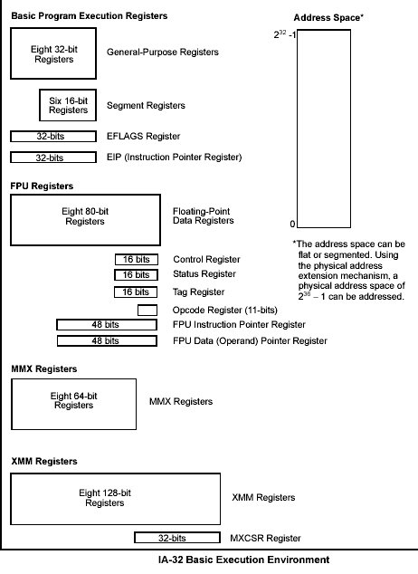
Das vorausgehende Bild zeigt die grundlegende Ausführungsumgebung für einen 32-Bit- IA32-Prozessor.
In addition to the resources provided in the basic execution environment, the IA-32 architecture provides the following system resources as part of its system-level architecture. They provide extensive support for operating-system and system-development software. Except for the I/O ports, the system resources are described in detail in the IA-32 Intel Architecture Software Developer s Manual, Volume 3: System Programming Guide.
The memory that the processor addresses on its bus is called physical memory. Physical memory is organized as a sequence of 8-bit bytes. Each byte is assigned a unique address, called a physical address. The physical address space ranges from zero to a maximum of 236 1 (64 GBytes). Virtually any operating system or executive designed to work with an IA-32 processor will use the processor s memory management facilities to access memory. These facilities provide features such as segmentation and paging, which allow memory to be managed efficiently and reliably. The following paragraphs describe the basic methods of addressing memory when memory management is used.
When employing the processor's memory management facilities, programs do not directly address physical memory. Instead, they access memory using any of three memory models: flat, segmented, or real-address mode. With the flat memory model memory appears to a program as a single, continuous address space, called a linear address space. Code (a program s instructions), data, and the procedure stack are all contained in this address space. The linear address space is byte addressable, with addresses running contiguously from 0 to 232-1. An address for any byte in the linear address space is called a linear address. With the segmented memory model, memory appears to a program as a group of independent address spaces called segments. When using this model, code, data, and stacks are typically contained in separate segments. To address a byte in a segment, a program must issue a logical address, which consists of a segment selector and an offset. (A logical address is often referred to as a far pointer.) The segment selector identifies the segment to be accessed and the offset identifies a byte in the address space of the segment. The programs running on an IA-32 processor can address up to 16,383 segments of different sizes and types, and each segment can be as large as 232 bytes. Internally, all the segments that are defined for a system are mapped into the processor's linear address space. To access a memory location, the processor thus translates each logical address into a linear address. This translation is transparent to the application program. The primary reason for using segmented memory is to increase the reliability of programs and systems. For example, placing a program s stack in a separate segment prevents the stack from growing into the code or data space and overwriting instructions or data, respectively. Placing the operating system s or executive s code, data, and stack in separate segments also protects them from the application program and vice versa. With the flat or the segmented memory model, the linear address space is mapped into the processor s physical address space either directly or through paging. When using direct mapping (paging disabled), each linear address has a one-to-one correspondence with a physical address (that is, linear addresses are sent out on the processor s address lines without translation). When using the IA-32 architecture's paging mechanism (paging enabled), the linear address space is divided into pages, which are mapped into virtual memory. The pages of virtual memory are then mapped as needed into physical memory. When an operating system or executive uses paging, the paging mechanism is transparent to an application program; that is, all the application program sees is the linear address space.
Im Falle der Intel IA32-CPUs werden also drei Arten von Adressen unterschieden (siehe auch das Schaubild):
Logische Adressen (logical address): bestehend aus Segment und Offset (Segmentnummer * 16 + Offset (32Bit-Zahl).
Lineare Adressen bzw. Virtuelle Adressen (linear addresses, virtual addresses): eine vorzeichenlose 32-Bit-Integerzahl (von 0x00000000 bis 0xffffffff).
Physikalische Adressen (physical addresses): diejenigen signale, durch die am Adressbus die Speicherzellen ausgewählt werden. Werden repräsentiert als vorzeichenlose 32-Bit Integerzahlen.
Modes of Operation vs. Memory Model When writing code for an IA-32 processor, a programmer needs to know the operating mode the processor is going to be in when executing the code and the memory model being used. The relationship between operating modes and memory models is as follows:

Speicheradressierung Intel
Logische Adressen werden im Segmentmodus von der Segmentationeinheit in lineare Adressen übersetzt. Diese werden dann von der Pagingeinheit in die entsprechenden Hardwareadressen übersetzt. Schliesslich gibt es meistens noch sogenannte Schiedseinheiten (arbiter units), die den multiplen Zugriff auf gleiche Speicherbereiche (mehrere CPUs, DMA) regeln.

Speicheradressierung
The processor provides 16 basic program execution registers for use in general system and application programing. Shown in the figure below, these registers can be grouped as follows:

General Purpose Registers
The 32-bit general-purpose registers EAX, EBX, ECX, EDX, ESI, EDI, EBP, and ESP are provided for holding the following items:
As shown in the Figurebelow, the lower 16 bits of the general-purpose registers map directly to the register set found in the 8086 and Intel 286 processors and can be referenced with the names AX, BX, CX, DX, BP, SI, DI, and SP. Each of the lower two bytes of the EAX, EBX, ECX, and EDX registers can be referenced by the names AH, BH, CH, and DH (high bytes) and AL, BL, CL, and DL (low bytes).
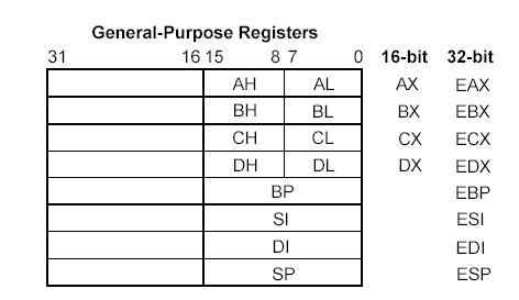
General Purpose Registers lower part
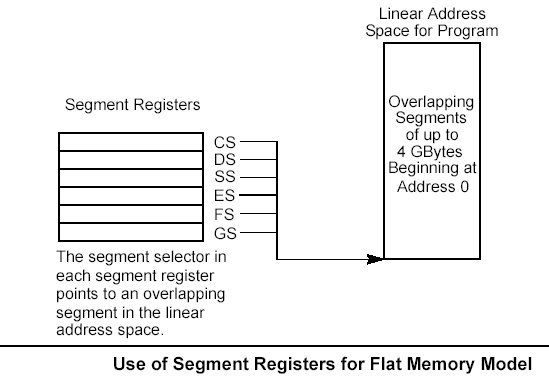
The segment registers (CS, DS, SS, ES, FS, and GS) hold 16-bit segment selectors. A segment selector is a special pointer that identifies a segment in memory. To access a particular segment in memory, the segment selector for that segment must be present in the appropriate segment register. When writing application code, programmers generally create segment selectors with assembler directives and symbols. The assembler and other tools then create the actual segment selector values associated with these directives and symbols. If writing system code, programmers may need to create segment selectors directly. How segment registers are used depends on the type of memory management model that the operating system or executive is using. When using the flat (unsegmented) memory model, the segment registers are loaded with segment selectors that point to overlapping segments, each of which begins at address 0 of the linear address space (as shown in the Figure below). These overlapping segments then comprise the linear address space for the program. Typically, two overlapping segments are defined: one for code and another for data and stacks. The CS segment register points to the code segment and all the other segment registers point to the data and stack segment. When using the segmented memory model, each segment register is ordinarily loaded with a different segment selector so that each segment register points to a different segment within the linear address space. At any time, a program can thus access up to six segments in the linear address space. To access a segment not pointed to by one of the segment registers, a program must first load the segment selector for the segment to be accessed into a segment register.
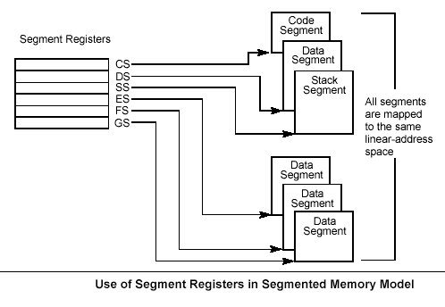
Each of the segment registers is associated with one of three types of storage: code, data, or stack. For example, the CS register contains the segment selector for the code segment, where the instructions being executed are stored. The processor fetches instructions from the code segment, using a logical address that consists of the segment selector in the CS register and the contents of the EIP register. The EIP register contains the offset within the code segment of the next instruction to be executed. The CS register cannot be loaded explicitly by an application program. Instead, it is loaded implicitly by instructions or internal processor operations that change program control (such as, procedure calls, interrupt handling, or task switching). The DS, ES, FS, and GS registers point to four data segments. The availability of four data segments permits efficient and secure access to different types of data structures. For example, four separate data segments might be created: one for the data structures of the current module, another for the data exported from a higher-level module, a third for a dynamically created data structure, and a fourth for data shared with another program. To access additional data segments, the application program must load segment selectors for these segments into the DS, ES, FS, and GS registers, as needed. The SS register contains the segment selector for the stack segment, where the procedure stack is stored for the program, task, or handler currently being executed. All stack operations use the SS register to find the stack segment. Unlike the CS register, the SS register can be loaded explicitly, which permits application programs to set up multiple stacks and switch among them. The four segment registers CS, DS, SS, and ES are the same as the segment registers found in the Intel 8086 and Intel 286 processors and the FS and GS registers were introduced into the IA-32 Architecture with the Intel386" family of processors.
The 32-bit EFLAGS register contains a group of status flags, a control flag, and a group of system flags. Figure 3-7 defines the flags within this register. Following initialization of the processor (either by asserting the RESET pin or the INIT pin), the state of the EFLAGS register is 00000002H. Bits 1, 3, 5, 15, and 22 through 31 of this register are reserved. Software should not use or depend on the states of any of these bits. Some of the flags in the EFLAGS register can be modified directly, using special-purpose instructions (described in the following sections). There are no instructions that allow the whole register to be examined or modified directly. The following instructions can be used to move groups of flags to and from the procedure stack or the EAX register: LAHF, SAHF, PUSHF, PUSHFD, POPF, and POPFD. After the contents of the EFLAGS register have been transferred to the procedure stack or EAX register, the flags can be examined and modified using the processor s bit manipulation instructions (BT, BTS, BTR, and BTC). When suspending a task (using the processor s multitasking facilities), the processor automatically saves the state of the EFLAGS register in the task state segment (TSS) for the task being suspended. When binding itself to a new task, the processor loads the EFLAGS register with data from the new task s TSS. When a call is made to an interrupt or exception handler procedure, the processor automatically saves the state of the EFLAGS registers on the procedure stack. When an interrupt or exception is handled with a task switch, the state of the EFLAGS register is saved in the TSS for the task being suspended.
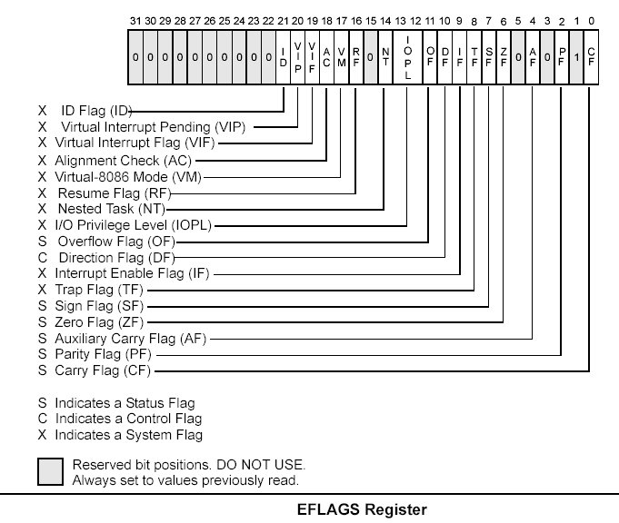
Vol. 1 3-13 The status flags (bits 0, 2, 4, 6, 7, and 11) of the EFLAGS register indicate the results of arithmetic instructions, such as the ADD, SUB, MUL, and DIV instructions. The status flag functions are: CF (bit 0) Carry flag. Set if an arithmetic operation generates a carry or a borrow out of the most-significant bit of the result; cleared otherwise. This flag indicates an overflow condition for unsigned-integer arithmetic. It is also used in multiple-precision arithmetic. PF (bit 2) Parity flag. Set if the least-significant byte of the result contains an even number of 1 bits; cleared otherwise. 3-14 Vol. 1 BASIC EXECUTION ENVIRONMENT AF (bit 4) Adjust flag. Set if an arithmetic operation generates a carry or a borrow out of bit 3 of the result; cleared otherwise. This flag is used in binary-coded decimal (BCD) arithmetic. ZF (bit 6) Zero flag. Set if the result is zero; cleared otherwise. SF (bit 7) Sign flag. Set equal to the most-significant bit of the result, which is the sign bit of a signed integer. (0 indicates a positive value and 1 indicates a negative value.) OF (bit 11) Overflow flag. Set if the integer result is too large a positive number or too small a negative number (excluding the sign-bit) to fit in the destination operand; cleared otherwise. This flag indicates an overflow condition for signed-integer (two s complement) arithmetic. Of these status flags, only the CF flag can be modified directly, using the STC, CLC, and CMC instructions. Also the bit instructions (BT, BTS, BTR, and BTC) copy a specified bit into the CF flag. The status flags allow a single arithmetic operation to produce results for three different data types: unsigned integers, signed integers, and BCD integers. If the result of an arithmetic operation is treated as an unsigned integer, the CF flag indicates an out-of-range condition (carry or a borrow); if treated as a signed integer (two s complement number), the OF flag indicates a carry or borrow; and if treated as a BCD digit, the AF flag indicates a carry or borrow. The SF flag indicates the sign of a signed integer. The ZF flag indicates either a signed- or an unsignedinteger zero. When performing multiple-precision arithmetic on integers, the CF flag is used in conjunction with the add with carry (ADC) and subtract with borrow (SBB) instructions to propagate a carry or borrow from one computation to the next. The condition instructions Jcc (jump on condition code cc), SETcc (byte set on condition code cc), LOOPcc, and CMOVcc (conditional move) use one or more of the status flags as condition codes and test them for branch, set-byte, or end-loop conditions. 3.4.3.2. DF FLAG The direction flag (DF, located in bit 10 of the EFLAGS register) controls string instructions (MOVS, CMPS, SCAS, LODS, and STOS). Setting the DF flag causes the string instructions to auto-decrement (to process strings from high addresses to low addresses). Clearing the DF flag causes the string instructions to auto-increment (process strings from low addresses to high addresses). The STD and CLD instructions set and clear the DF flag, respectively. BASIC EXECUTION ENVIRONMENT 3.4.4. System Flags and IOPL Field The system flags and IOPL field in the EFLAGS register control operating-system or executive operations. They should not be modified by application programs. The functions of the system flags are as follows: IF (bit 9) Interrupt enable flag. Controls the response of the processor to maskable interrupt requests. Set to respond to maskable interrupts; cleared to inhibit maskable interrupts. TF (bit 8) Trap flag. Set to enable single-step mode for debugging; clear to disable single-step mode. IOPL (bits 12 and 13) I/O privilege level field. Indicates the I/O privilege level of the currently running program or task. The current privilege level (CPL) of the currently running program or task must be less than or equal to the I/O privilege level to access the I/O address space. This field can only be modified by the POPF and IRET instructions when operating at a CPL of 0. NT (bit 14) Nested task flag. Controls the chaining of interrupted and called tasks. Set when the current task is linked to the previously executed task; cleared when the current task is not linked to another task. RF (bit 16) Resume flag. Controls the processor s response to debug exceptions. VM (bit 17) Virtual-8086 mode flag. Set to enable virtual-8086 mode; clear to return to protected mode without virtual-8086 mode semantics. AC (bit 18) Alignment check flag. Set this flag and the AM bit in the CR0 register to enable alignment checking of memory references; clear the AC flag and/or the AM bit to disable alignment checking. VIF (bit 19) Virtual interrupt flag. Virtual image of the IF flag. Used in conjunction with the VIP flag. (To use this flag and the VIP flag the virtual mode extensions are enabled by setting the VME flag in control register CR4.) VIP (bit 20) Virtual interrupt pending flag. Set to indicate that an interrupt is pending; clear when no interrupt is pending. (Software sets and clears this flag; the processor only reads it.) Used in conjunction with the VIF flag. ID (bit 21) Identification flag. The ability of a program to set or clear this flag indicates support for the CPUID instruction.
Fragen zum Bootstrap und Linux:
Was versteht man unter einem Bootstrap?
Welche Ereignisse werden in einem PC nach Betätigung des Resetschalters ausgelöst?
Was versteht man unter POST?
Was sind die wichtigsten Phasen der Bootroutine bei Linux ?
Was wird durch die Bootroutine bei Linux erreicht?
Was unterscheidet den User Mode vom Kernel Mode bei Linux?
Auf welche Weise kann die Aussenwelt den Kernelmode von Linux beeinflussen?
Was unterscheidet einen Prozess, der reentrant ist, von einem Prozess, der nicht reentrant ist?
Geht man von den Prozessen als Grundelementen des Linux-Kernels aus: welche Möglichkeiten bestehen aus Sicht des Kernels, Prozesse zu synchronisieren?
Wann benötigt man Warteschlagen für Prozesse?
Was ist der Unterschied zwischen einem präemptiven und einem nicht-präemptiven Kernel?
Fragen zur IA32-Architektur
Welche Elemente bilden die normale Ausführungsumgebung für einen IA32-CPU (Register,..., Ports,..., Memory,...?
Was unterscheidet ein Segment-Speichermodell (segmented memory) von einem Flachen Speichermodell (flat memory)?
Was ist der Unterschied zwischen physikalischen, logischen und Linearen Adressen?
Was ist der Unterschied zwischen protected mode und real-address mode?
Wozu werden die general purpose registers benutzt?
Wozu werden die segment registers benutzt?
Wozu wird das eflags register benutzt?