|
|
I-PROGR3 WS03 - PROGRAMMIEREN3 - Vorlesung mit Übung
|
In der vorausgehenden Vorlesung wurde gesagt, dass wir uns am Paradigma des Softwareengineerings orientieren wollen, und hier speziell am Paradigma des objektorientierten Sofftwareengineerings. Eine Grundidee des objektorientierten Programmierens besteht darin, dass man das zu lösende Problem dadurch strukturiert, dass man es in beteiligte Objekte zerlegt, denen abstrakte Klassen korrespondieren. Diese 'Objekt-Analyse' geht dem eigentlichen Implementieren voraus und ist von der späteren Implementierung idealerweise weitgehend unabhängig. Für die Modellbildung sollte es egal sein, ob die Implementierung später C++, Java, Ada, Smalltalk oder irgendeine andere Sprache wählt. Selbst eine Umsetzung in eine nicht objektorientierte Sprache wie z.B. C sollte prinzipiell möglich sein. In der Praxis sieht es allerdings so aus, dass sehr oft die spätere Zielarchitektur samt einer bestimmten Sprache schon bei der Analyse berücksichtigt wird. Trotz einiger Mängel hat sich für bestimmte Anwendungsfelder heute durchgesetzt, die objektorientierte Analyse mit der standardisierten UML-Notation vorzunehmen, und von dieser aus dann die Implementierung zu starten (Für UML siehe allgemein OMG UML-Homepage).
In der Vorlesung Programmieren2 ist der Einsatz von UML an einzelnen Beispielen zwar schon grundsätzlich gezeigt worden; in dieser Vorlesung Programmieren3 soll die Analyse mittels UML-Diagrammen konsequent auf alle Projekte ausgedehnt werden.
Als Werkzeug wird hierfür die frei verfügbare Software umbrello eingesetzt werden (Diese Software ist auch Teil der Linux-Distribution SuSe 8.2). Mit ihr kann man sehr leicht die wichtigsten UML-Diagramme erzeugen und daraus ersten Code für die verwendeten Klassen automatisch generieren. Unterstützt wird zur Zeit C++, Java und PHP. Die Kenntnis dieser Software wird für die Klausur vorausgesetzt.
Entsprechend dem Paradigma des Softwareengineerings aus Vorlesung Nr.1 betrachten wir ein erstes Problem und transformieren es schrittweise in einen beschriebenen Anwendungsfall, dann in ein Analysemodell, schliesslich in ausführbaren Code. Wir beginnen mit dem Anwendungsfall.
Unser Beispielproblem sei wie folgt umschrieben: wir haben ein System S1, das von seiner Umgebung E Eingaben I bekommen kann. Diese Eingaben können zu Zustandsänderungen des Systems S1 führen. Zwei Varianten werden angenommen:
Bei den Zuständen handelt es sich um ein Spielbrett B, auf dem ein Spielstein bewegt werden kann; bestimmten Eingaben entsprechen bestimmte Bewegungen des Spielsteins.
Bei den Zuständen handelt es sich um Ausdrücke einer Sprache L; bestimmten Eingaben entsprechen bestimmten Ausdrücken der Sprache L.
Dieses Problem soll jetzt mit Hilfe eines Anwendungsdiagramms und eines Anforderungskataloges weiter analysiert werden.
Zur Beschreibung der 'Grundidee' eines Anwendungsfall mag folgender Abschnitt aus der Dokumentation zu UML v1.5 dienen:
 "The purpose of a use case is to define a piece of behavior of an entity without revealing the internal
 structure of the entity. The entity specified in this way may be a system or any model element that
 contains behavior, like a subsystem or a class, in a model of a system. Each use case specifies a service
 the entity provides to its users; that is, a specific way of using the entity. The service, which is
 initiated by a user, is a complete sequence. This implies that after its performance the entity will in
 general be in a state in which the sequence can be initiated again. A use case describes the interactions
 between the users and the entity as well as the responses performed by the entity, as these responses are
 perceived from the outside of the entity. A use case also includes possible variants of this sequence
 (for example, alternative sequences, exceptional behavior, error handling, etc.). The complete set of use
 cases specifies all different ways to use the entity; that is, all behavior of the entity is expressed by
 its use cases. These use cases can be grouped into packages for convenience. From a pragmatic point of view,
 use cases can be used both for specification of the (external) requirements on an entity and for specification
 of the functionality offered by an (already realized) entity. Moreover, the use cases also indirectly state
 the requirements the specified entity poses on its users; that is, how they should interact so the entity will
 be able to perform its services". (UML 1.5, 2-136)
Für weitere Details sei auf den Text des Standards selbst verwiesen. Eine knappe Darstellung auf Deutsch findet sich auch im Hilfetext zum Werkzeug 'umbrello'.
Das erste Diagramm zeigt als Akteur die Umgebung E und als Aktivität 'board ändern'.
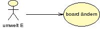
Anwendungsdiagramm zu Fall (i) Board
Das zweite Diagramm zeigt als Akteur wieder die Umgebung E und dieses Mal als Aktivität 'in einen Ausdruck der Sprache L ändern'.
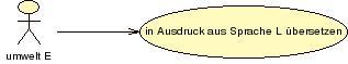
Anwendungsdiagramm zu Fall (ii) Sprache
In beiden Fällen werden Tätigkeiten beschrieben, die von einem Zustand zu einem anderen führen. Auslöser ist jeweils die Umgebung E.
Für eine Umsetzung wäre es jetzt notwendig, diese beiden Fälle detaillierter zu beschreiben. Dies wird an dieser Stelle unterlassen. Stattdessen wird versucht, mit den Mitteln von UML die beiden Fälle so weit als möglich weiter zu modellieren. Fehlende Informationen werden dann nach Bedarf hinzugefügt.
Nach Fixierung des Anwendungsfalles müssen jetzt diese allgemeinen Annahmen weiter konkretisiert werden. Üblicherweise betrachtet man zuerst die statischen Elemente des Systems, dann seine Dynamik.
Als statische Elemente zählen die beteiligten Objekte bzw. die den Objekten korrespondierenden Klassen.
Im ersten Fall legt sich nahe eine Klasse 'Board' anzunehmen; im zweiten Fall eine Klasse 'Translator'. In beiden Fällen soll die Modellierung mit Hilfe eines Klassendiasgramms erfolgen.
Der UML-Standard schreibt zum Klassendiagramm folgendes:
"A class diagram is a graph of Classifier elements connected by their various static relationships. Note that a
class  diagram may also contain interfaces, packages, relationships, and even instances, such as objects and links.
Perhaps a better name would be  static structural diagram  but  class diagram  is shorter and well established. "
(siehe: OMG-Unified Modeling Language, v1.5 March 2003, 3-34)
Es wird erläutert, dass Klassen nur eines unter mehreren Elementen sind, die in einem Klassendiagramm vorkommen können. Hier die Erklärung des begrifflichen Zusammenhanges:
"Classifier is the metamodel superclass of Class, DataType, and Interface. All of these have similar syntax and are
therefore all notated using the rectangle symbol with keywords used as necessary. Because classes are most common
in diagrams, a rectangle without a keyword represents a class, and the other subclasses of Classifier are
indicated with keywords."
(siehe: OMG-Unified Modeling Language, v1.5 March 2003, 3-35)
Die Klasse selbst wird dann wie folgt beschrieben:
"A class is the descriptor for a set of objects with similar structure, behavior, and relationships. The model is
concerned with describing the intension of the class, that is, the rules that define it. The run-time execution
provides its extension, that is, its instances. UML provides notation for declaring classes and specifying their
properties, as well as using classes in various ways. Some modeling elements that are similar in form to classes
(such as interfaces, signals, or utilities) are notated using keywords on class symbols; some of these are separate
metamodel classes and some are stereotypes of Class. Classes are declared in class diagrams and used in most other
diagrams. UML provides a graphical notation for declaring and using classes, as well as a textual notation for
referencing classes within the descriptions of other model elements."
(siehe: OMG-Unified Modeling Language, v1.5 March 2003, 3-35)
Zur Notation von Klassendiagrammen heisst es:
"A class diagram is a collection of static declarative model elements, such as classes, interfaces, and their
relationships, connected as a graph to each other and to their contents. Class diagrams may be organized into
packages either with their underlying models or as separate packages that build upon the underlying model packages."
(siehe: OMG-Unified Modeling Language, v1.5 March 2003, 3-34)
Zur Notation von Klassen:
"A class is drawn as a solid-outline rectangle with three compartments separated by horizontal lines. The top name
compartment holds the class name and other general properties of the class (including stereotype); the middle list
compartment holds a list of attributes; the bottom list compartment holds a list of operations."
(siehe: OMG-Unified Modeling Language, v1.5 March 2003, 3-36)
Operation (Methode) einer Klasse:
"An operation is a service that an instance of the class may be requested to perform. It has a name and a list of
arguments."
 (siehe: OMG-Unified Modeling Language, v1.5 March 2003, 3-44)
Operationen werden wie folgt notiert:
"An operation is shown as a text string that can be parsed into the various properties of an operation model element.
The default syntax is:

visibility name ( parameter-list ) : return-type-expression { property-string }
(siehe: OMG-Unified Modeling Language, v1.5 March 2003, 3-44)
Für die Details dieser Notation sei auf den Standard verwiesen. Interessant sind allerdings die Möglichkeiten, die maximalen Forderungen nach Bedarf zu vereinfachen:
"The argument list and return type may be suppressed (together, not separately).

A tool may show the visibility indication in a different way, such as by using a special icon or by sorting the elements
by group.

The syntax of the operation signature string can be that of a particular programming language, such as C++ or Smalltalk.

Specific tagged properties may be included in the string. A procedure body for a method may be shown in a note
attached to the operation entry within the compartment (Figure 3-24 on page 3-47). The line is drawn to the string
within the compartment. This approach is useful mainly for showing small method bodies."
(siehe: OMG-Unified Modeling Language, v1.5 March 2003, 3-46)
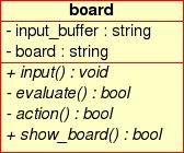
Klasse 'Board' von Fall (i)
Die Klasse Board ist so konstruiert, dass man mit der öffentlichen Funktion 'input()' einen String von der Umgebung E als Eingabe in das System eingeben kann. Diese Eingabe wird zunächst in ein privates Eingaberegister 'input_buffer' zwischengespeichert. Die private Funktion 'evaluate()' analysiert dann diese Eingabe. Abhängig vom Ergebnis führt dann die private Funktion 'action()' eine Aktion 'action()' aus. Dies bedeutet, dass ein Spielstein auf dem Board eingeführt, ein Spielstein bewegt oder ein Spielstein entfernt werden kann. Alle Aktionen beziehen sich auf die private Variable 'board'. Schliesslich kann die öffentliche Funktion 'show_board()' den Zustand des Boards anzeigen.
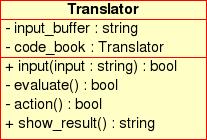
Klasse 'Translator' von Fall (ii)
Die Klasse 'Translator' sehr ähnlich konstruiert wie die Klasse 'Board'. Mit der öffentlichen Funktion 'input()' kann man einen String von der Umgebung E als Eingabe in das System eingeben. Diese Eingabe wird zunächst in ein privates Eingaberegister 'input_buffer' zwischengespeichert. Die private Funktion 'evaluate()' analysiert dann diese Eingabe. Abhängig vom Ergebnis führt dann die private Funktion 'action()' eine Aktion 'action()' aus. Dies bedeutet, dass entsprechend der Eingabe ein bestimmter Ausdruck einer Sprache L erzeugt wird. Alle Aktionen beziehen sich auf die private Variable 'code_book'. Schliesslich kann die öffentliche Funktion 'show_result()' den aktuellen Ausdruck in Abhängigkeit von der aktuellen Eingabe anzeigen.
Für die Analyse der Dynamik eines System bietet das Werkzeug umbrello vier unterschiedliche Diagramme an: Kollaboration, Sequenz, Aktion sowie Zustand. Am aussagekräftigsten sind Sequenz, Aktion sowie Zustand, wobei alle drei formal betrachtet redundant sind. Von daher ist es letztlich egal, welches der drei Diagramme man wählt. Wir benutzen zunächst nur das Sequenzendiagramm zur Analyse der Dynamik des Systems.
Eine kurze Charakterisierung der Grundidee von Sequenzdiagrammen lautet im UML-Standard wie folgt:
"In a sequence diagram an object lifeline denotes an Instance playing a specific role. Arrows between the lifelines
denote communication between the Instances playing those roles. Within a sequence diagram the existence and duration
of the Instance in a  role is shown, but the relationships among the Instances are not shown.
The role is specified by a ClassifierRole; it describes the properties of an Instance playing the role and describes
the relationships an Instance in that role has to other Instances."
(siehe: OMG-Unified Modeling Language, v1.5 March 2003, pp.3-108)
Zur Notation heisst es:
"An Instance is shown as a vertical dashed line called the  lifeline.  The lifeline represents the existence
of the Instance at a particular time. If the Instance is created or destroyed during the period of time shown on the
diagram, then its lifeline starts or stops at the appropriate point; otherwise, it goes from the top to the bottom of
the diagram. An object symbol is drawn at the head of the lifeline. If the Instance is created during the diagram,
then the arrow, which maps onto the Stimulus that creates the Instance, is drawn with its arrowhead on the object
symbol. If the Instance is destroyed during the diagram, then its destruction is marked by a large  X,  either at
the arrow mapping to the Stimulus that causes the destruction or (in the case of selfdestruction) at the final return
arrow from the destroyed Instance. An Instance that exists when the transaction starts is shown at the top of the
diagram (above the first arrow), while an Instance that exists when the transaction finishes has its lifeline continue
beyond the final arrow. The lifeline may split into two or more concurrent lifelines to show conditionality. Each
separate track corresponds to a conditional branch in the communication. The lifelines may merge together at some
subsequent point."
(siehe: OMG-Unified Modeling Language, v1.5 March 2003, pp.3-109)
Für Objekte gilt allgemein:
"An object represents a particular instance of a class. It has identity and attribute values. A similar notation
also represents a role within a collaboration because roles have instance-like characteristics."
(siehe: OMG-Unified Modeling Language, v1.5 March 2003, pp.3-64)
Zur Notation von Objekten heisst es:
"The object notation is derived from the class notation by underlining instance-level elements, as explained in the
general comments in Section 3.12,  Type-Instance Correspondence,  on page 3-14. An object shown as a rectangle with
two compartments.  The top compartment shows the name of the object and its class, all underlined, using the syntax:

objectname : classname

The classname can include a full pathname of enclosing package, if necessary. The package names precede the classname
and are separated by double colons. For example:

display_window: WindowingSystem::GraphicWindows::Window

A stereotype for the class may be shown textually (in guillemets above the name string) or as an icon in the upper right
corner. The stereotype for an object must match the stereotype for its class. To show multiple classes that the object
is an instance of, use a comma-separated list of classnames. These classnames must be legal for multiple classification;
that is, only one implementation class permitted, but multiple types permitted. To show the presence of an object
in a particular state of a class, use the syntax:

objectname : classname  [  statename-list  ]

The list must be a comma-separated list of names of states that can legally occur concurrently. The second compartment
shows the attributes for the object and their values as a list. Each value line has the syntax:

attributename : type = value

The type is redundant with the attribute declaration in the class and may be omitted. The value is specified as
a literal value. UML does not specify the syntax for literal value expressions; however, it is expected that a tool
will specify such a syntax using some programming language.

The flow relationship between two values of the same object over time can be shown by connecting two object symbols
by a dashed arrow with the keyword «become». If the flow arrow is on a collaboration diagram, the label may also include
a sequence number to show when the value changes. Similarly, the keyword «copy» can be used to show the creation of
one object from another object value.
(siehe: OMG-Unified Modeling Language, v1.5 March 2003, pp.3-64f)
Die Kommunikation zwischen Instanzen wird wie folgt beschrieben:
"A Stimulus is a communication between two Instances that conveys information with the expectation that action
will ensue. A Stimulus will cause an Operation to be invoked, raise a Signal, or cause an Instance to be created
or destroyed. A Message is a specification of Stimulus, i.e. it specifies the roles that the sender and the receiver
Instances must conform to, as well as the Procedure which will, when executed, dispatch a Stimulus that conforms to
the Message."
(siehe: OMG-Unified Modeling Language, v1.5 March 2003, pp.3-111)
Zur Notation von Kommunikationsereignissen heisst es:
"filled solid arrowhead:
 Operation call or other nested flow of control. The entire nested sequence is completed before the outer level sequence
 resumes. The arrowhead may be used to denote ordinary operation calls, but it may also be used to denote concurrently
 active instances when one of them sends a Signal and waits for a nested sequence of behavior to complete before it
 continues.

 stick arrowhead (wird im Diagramm unten benutzt):
 Asynchronous communication; that is, no nesting of control. The sender dispatches the Stimulus and immediately
 continues with the next step in the execution.

 dashed arrow with stick arrowhead:
  Return from operation call.

 Variation:
 In a procedural flow of control, the return arrow may be omitted (it is implicit at the end of an activation). It
 is assumed that every call has a paired return after any subordinate stimuli. The return value can be shown on the
 initial arrow. For nonprocedural flow of control (including parallel processing and asynchronous messages) returns
 should be shown explicitly.

 Variation:
 Normally message arrows are drawn horizontally. This indicates the duration required to send the stimulus is
 atomic;  that is, it is brief compared to the granularity of the interaction and that nothing else can  happen
 during the transmission of the stimulus. This is the correct assumption within many computers. If the stimulus
 requires some time to arrive, during which something else can occur (such as a stimulus in the opposite direction),
 then the arrow may be slanted downward so that the arrowhead is below the arrow tail.

 Variation:
 Branching A branch is shown by multiple arrows leaving a single point, each possibly labeled by a condition.
 Depending on whether the conditions are mutually exclusive, the construct may represent conditionality or concurrency.

Variation:
Iteration A connected set of arrows may be enclosed and marked as an iteration. For a generic sequence diagram,
the iteration indicates that the dispatch of a set of stimuli can occur multiple times. For a procedure, the
continuation condition for the iteration may be specified at the bottom of the iteration. If there is concurrency,
then some arrows in the diagram may be part of the iteration and others may be single execution. It is desirable
to arrange a diagram so that the arrows in the iteration can be enclosed together easily.

Variation:
A lifeline may subsume an entire set of objects on a diagram representing a highlevel view.

Variation:
A distinction may be made between a period during which an Instance has a live activation and a period in which
the activation is actually computing. The former (during which it has control information on a stack but during which
control resides in something that it called) is shown with the ordinary double line. The latter (during which it
is the top item on the stack) may be distinguished by shading the region."
(siehe: OMG-Unified Modeling Language, v1.5 March 2003, pp.3-112f)
Entsprechend diesen Konventionen kann mit umbrello ein einfaches Sequenzendiagramm erzeugt werden. Zu beachten ist dabei, dass nicht die Klassen Botschaften austauschen, sondern Instanzen der Klassen, konkrete Objekte. Objekte werden in UML dadurch gekennzeichnet, dass sie unterstrichen sind.
Im Sequenzdiagramm wird angenommen, dass zur Klasse umwelt eine Instanz umw1 gebildet worden ist, also das Objekt umw1:umwelt; dieses Objekt ist zusätzlich als Akteur charakterisiert. Zusätzlich wurde eine Instanz b1 der Klasse board angenommen, also das Objekt b1:board. Die Umwelt kann nun mittels der öffentlichen Methode input() von b1 eine Eingabe zum Objekt b1 schicken, also daher der Aufruf b1.input(). Das Objekt b1:board kann auf sich selbst die privaten Methoden b1.evaluate() und b1.action() anwenden. Mittels der öffentlichen Methode show_board() von b1 kann das Objekt umw1:umwelt1 dann das Ergebnis der internen Aktionen auf dem Board anzeigen.
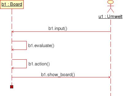
Sequenzdiagramm zu Fall (i) Board
Das Sequenzdiagramm für Fall (ii) ist ganz analog.
Das Credo des Softwareengineerings heute lautet: 'Je besser die Modellierung, umso schneller und sicherer die anschliessende Implementierung'. Dies ist sicher richtig, wenn es eine vollständige automatische Übersetzung der Modelle in den Quelltext der Zielplattform gäbe und wenn man schon bei der Implementierung sämtliche Details konkreter Plattformen in der Modellierung vorwegnehmen könnte, einschliesslich angemessener Tests. Davon ist das Softwareengineering aber leider noch weit entfernt. Für Einzelheiten dieser Problematik sei wieder auf die kommenden Vorlesungen zum Softwareengineering verwiesen.
Im vorliegenden Fall sehen wir von sehr vielen wichtigen Randbedingungen der Implementierung ab und konzentrieren uns auf die unmittelbare Umsetzung derjenigen Modelle, die uns das Werkzeug umbrello zur Verfügung stellt.
Bislang benutzen wir drei Modelle: Anwandungsfalldiagramm ('use case'), Klassendiagramm und Sequenzdiagramm. Das nachfolgende Schaubild zeigt an, wie sich die Implementierungsdimension zu diesen Modellen verhält:

Übersicht Modellierung und Implementierung
Im Schaubild ist die Modellierungs-Dimension und die Implementierungs-Dimension gegenüber gestellt: man kann erkennen, dass den Klassendiagrammen auf der Quelltextseite --in unserem Fall C++- zwei Arten von Dateien entsprechen: die Headerdateien mit der Endung '.hpp' (vielfach auch nur '.h'), die C++-Übersetzungen der UML-Klassen entsprechen, sowie die Implementierungsdateien mit der Endung '.cpp', die Konkretisierungen der Elementfunktionen (Operationen, Methoden) der Klassen darstellen.
Man sieht ferner, dass es zusätzlich zu diesen C++-Dateien noch mindestens eine andere Datei gibt, die im Diagramm '___-usage.cpp' genannt wird. Dies ergibt sich daraus, dass konkrete Aktionen nicht mit den Klassen als solchen stattfinden können, sondern nur mit den Instanzen der Klassen, mit den Objekten. Auf der Modellierungsseite wird dies im Sequenzdiagramm zum Ausdruck gebracht. Hier werden keine Klassen, sondern Instanzen der zuvor eingeführten Klassen benutzt, um irgendwelche Aktionen auszuführen. Ferner wird im Sequenzdiagramm auch festgelegt, in welcher Abfolge die Aktionen stattfinden sollen.
Auf der Quelltextseite benötigt man dann eine Datei, die diese Ebene der Objekte und deren Aktionen widerspiegelt; dies ist die hier mit '____-usage.cpp' bezeichnet Datei (in der Literatur oft auch 'Testdatei' genannt). Die usage-Datei setzt die Definition der Klassen und deren Realisierung voraus. In ihr werden auf der Basis dieser Klassen Instanzen, also Objekte, eingeführt, und dann lässt man diese Objekte 'arbeiten', und zwar so, wie dies im Sequenzdiagramm vorgeschrieben wird.
Die Erzeugung des Quelltextes der Klassen wird vom Werkzeug umbrello teilweise unterstützt. So kann man die .hpp-Dateien --bei umbrello .h-Dateien-- automatisch erzeugen lassen. Dies geht über den Menüpunkt 'Quelltext'. Die Erzeugung der Quelltext wird dabei gesteuert über eine Templatedatei:
/opt/kde3/share/apps/umbrello/headings/heading.h
In dieser Datei kann man festlegen, wie der Header aussehen soll. Das folgende Beispiel benutzt diese Headerdatei zunächst unverändert:
/************************************************************************
  			board.h - Copyright gerd

Here you can write a license for your code, some comments or any other
information you want to have in your generated code. To to this simply
configure the "headings" directory in uml to point to a directory
where you have your heading files.

or you can just replace the contents of this file with your own.
If you want to do this, this file is located at

/opt/kde3/share/apps/umbrello/headings/heading.h

-->Code Generators searches for heading files based on the file extension
   i.e. it will look for a file name ending in ".h" to include in C++ header
   files, and for a file name ending in ".java" to include in all generated
   java code.
   If you name the file "heading.<extension>", Code Generator will always
   choose this file even if there are other files with the same extension in the
   directory. If you name the file something else, it must be the only one with that
   extension in the directory to guarantee that Code Generator will choose it.

you can use variables in your heading files which are replaced at generation
time. possible variables are : author, date, time, filename and filepath.
just write %variable_name%

This file was generated on Mon Okt 13 2003 at 21:59:54
The original location of this file is /home/gerd/public_html/fh/I-PROGR3/I-PROGR3-EX/EX2/board.h
**************************************************************************/


#ifndef BOARD_H
#define BOARD_H


/**
  * class board
  *
  */

class board
{

/** Public methods: */
public:
    /**
      *
      */
    void input(  );

    /**
      *
      */
    bool show_board(  );


/** Private methods: */
private:
    /**
      *
      */
    bool evaluate(  );

    /**
      *
      */
    bool action(  );


/**Attributes: */

private:
    /**
      * Speichert Daten aus Umgebung zwischen
      */
    string input_buffer;
    /**
      * Enthält alle Zustände des Boards
      */
    string board;

};

#endif // BOARD_H
Man kann erkennen, dass im Falle der .h-Dateien sämtliche Attribute und Methoden übernommen worden sind, zusätzlich auch alle Kommentare, die man schon in umbrello eingefügt hat. Im Falle der .cpp-Dateien (siehe weiter unten), in denen die Realisierung der Methoden beschrieben werden muss, bleiben die Funktionsrümpfe allerdings leer; dies bedeutet, hier muss der Entwickler selbst noch 'Hand anlegen'.
/************************************************************************
  			board.cpp - Copyright gerd

Here you can write a license for your code, some comments or any other
information you want to have in your generated code. To to this simply
configure the "headings" directory in uml to point to a directory
where you have your heading files.

or you can just replace the contents of this file with your own.
If you want to do this, this file is located at

/opt/kde3/share/apps/umbrello/headings/heading.cpp

-->Code Generators searches for heading files based on the file extension
   i.e. it will look for a file name ending in ".h" to include in C++ header
   files, and for a file name ending in ".java" to include in all generated
   java code.
   If you name the file "heading.<extension>", Code Generator will always
   choose this file even if there are other files with the same extension in the
   directory. If you name the file something else, it must be the only one with that
   extension in the directory to guarantee that Code Generator will choose it.

you can use variables in your heading files which are replaced at generation
time. possible variables are : author, date, time, filename and filepath.
just write %variable_name%

This file was generated on Mon Okt 13 2003 at 21:59:54
The original location of this file is /home/gerd/public_html/fh/I-PROGR3/I-PROGR3-EX/EX2/board.cpp
**************************************************************************/


#include "board.h"

void board::input(  )
{

}


bool board::show_board(  )
{

}


bool board::evaluate(  )
{

}


bool board::action(  )
{

}
Auf eine Besonderheit beim Einsatz von umbrello zur Quelltexterzeugung sei aber noch hingewiessen: falls man Sequenzdiagramme erzeugen will, dann sollte man die Klassendiagramme erst anschliessend auf der Basis der Sequenzdiagramme erzeugen, da umbrello aus dem Sequenzdiagramm heraus die beteiligten Klassen (und Objekte) als Rümpfe anlegt; namensgleiche Klassen aus vorausgehenden Klassendiagrammen werden als Konflikte angezeigt. Daraus folgt, dass man beim Einsatz von umbrello im Rahmen der Modellierung nach dem Anwendungsfall zuerst das Sequenzdiagramm modellieren muss und aufbauend auf den hierbei benutzten Klassen die Details der beteiligten Klassen. Andererseits werden die im Rahmen eines Sequenzdiagramms erzeugten Klassen nicht als Diagramm angezeigt. Hier bleiben momentan nur 'workarounds'...
Um die bislang definierten Klassen zu nutzen, wird hier eine kleine Usage-Datei definiert, die das Sequenz-Diagramm nur insoweit umsetzt, als die öffentlichen Methoden betroffen sind; diese definieren gerade die Schnittstelle zum User, d.h. zur Umwelt.
/********************************************
 *
 * board:usage.cpp
 *
 ****************************************************
 *
 * Einfache Realisierung des Sequenzdiagramms
 * beschränkt auf die öffentlichen Methoden
 *
 *******************************************************/

#include "board.h"


int main(void)
{
  /******* Die Umgebung, repräsentiert durch einen Benutzer, kann
   ******* Eingaben in ein Board vornehmen. Das Board interpretiert die
   ******* Eingaben und führt geeignete Aktionen aus. nach jeder
   ******* Aktion wird das veränderte Board angezeigt.
   *******/

  Board b1;

  b1.input();

  b1.show_board();


}
Damit diese Usage-Datei ausgeführt werden kann, muss man die Implementierung der Klasse 'board' 'per Hand' weiter vorantreiben. Dies geschieht in der Datei 'board2.cpp'.
Für den Test wurden die Methoden mit minimalen Aktionen aufgeladen. Hier das einfache Beispiel:
/************************************************************************
  			board2.cpp - Copyright gerd

This file was generated on Mon Okt 13 2003 at 21:59:54
The original location of this file is /home/gerd/public_html/fh/I-PROGR3/I-PROGR3-EX/EX2/board.cpp
**************************************************************************/


#include "board.h"

#include <iostream>
#include <string>

using namespace std;

void board::input(  )
{
  cout << "BITTE EINGABE FÜR INPUT : ";
  cin >> input_buffer;

  /**********************
   *
   * Interne Auswertung und Aktion
   *
   ********************************/

  board::evaluate();
  board::action();

}


bool board::show_board(  )
{
  cout << "show_board : " << board << endl;

}


bool board::evaluate(  )
{
  if(input_buffer == "Hallo") {cout<< "evaluate() : Hallo TRUE "<< endl; board = "HALLO!"; }
  else{cout << "evaluate() : Hallo FALSE " << endl; board = "NOT-HALLO!"; }
}


bool board::action(  )
{
  cout << "action() : keine eigene Aktion " << endl;;
}
Einfacher Test des bisherigen Programms:
gerd@kant:~/public_html/fh/I-PROGR3/I-PROGR3-EX/EX2> g++ -o board board-usage.cpp board2.cpp
gerd@kant:~/public_html/fh/I-PROGR3/I-PROGR3-EX/EX2> ./board
BITTE EINGABE FÜR INPUT : etetetet
evaluate() : Hallo FALSE
action() : keine eigene Aktion
show_board : NOT-HALLO!
gerd@kant:~/public_html/fh/I-PROGR3/I-PROGR3-EX/EX2> ./board
BITTE EINGABE FÜR INPUT : Hallo
evaluate() : Hallo TRUE
action() : keine eigene Aktion
show_board : HALLO!
gerd@kant:~/public_html/fh/I-PROGR3/I-PROGR3-EX/EX2>
In den Übungen