Figure 1
SIGPLAN Notices 12 1973 August
technical contributions
FLOWCHART TECHNIQUES FOR STRUCTURED PROGRAMMING
I. Nassi
and
B. Shneiderman
Department of Computer Science
State University of New York at Stony Brook
Stony Brook, L. I., New York
ABSTRACT
With the advent of structured programming and GOTO-less programming, a method is needed to model computation in simply ordered structures, each representing a complete thought possibly defined in terms of other thoughts as yet undefined. A model is needed which prevents unrestricted transfers of control and has a control structure closer to languages amenable to structured programming. We present an attempt at such a model.
Typically, computer programs go through various phases of formulation and definition. During one of these phases a flowchart may be drawn to describe the program at a level of abstraction somewhere between the problem statement and the code of the completed program. The programmer designs the flowchart in such a way that it can be coded easily into a convenient programming language, yet keeps the underlying algorithm sufficiently transparent to think about in modular terms. Unfortunately the conventional flowchart language has aspects that make it both too powerful and yet too simple a language to model current programming techniques. These techniques tend toward a more restrictive control structure which the flowchart cannot describe nicely. Certain control structures in programming languages, such as iteration, have no direct translation to flowchart language and must be built from simpler control structures, thereby losing the forest in the trees. On the other hand, the power the unrestricted GOTO affords presents problems in logical analysis of programs and program verification, optimization, and debugging. The translation from flowchart to computer program is a one to many relationship whose output ranges over programs only some of which are legible, concise, and efficient.
Top-down programming as defined by Mills (1) (or the top-down modularization of Wulf et al (2)) is the technique of analyzing an idea to form simpler ideas, and recursively applying the technique.
These ideas may take the form of programs, subroutines, macros, lines of code, or other modular forms. Dijkstra?s structured programming (3) organizes program components into levels which he calls pearls, and strings them together into a necklace (read "programs"). In addition, Dijkstra proposes abolishing the use of unrestricted GOTOs to help prevent unwieldy programs which are difficult to analyze (4).
The theoretical basis for our representation of structured programs was given by Bohm and Jacopini (5). They described a flowchart language whose alphabet consisted of

Figure 1
and then proceeded to prove that any program written in that language could also be written in a modified
subset of that language whose alphabet consists only of

Figure 2
and interpreted processes on a Boolean stack:
K(v, w) = w
T(w) = (t, w)
F(w) = (f, w)
w (v, w) = v v e {t, f}
Note that any program in the subset language is a program in the flowchart language, and that no arbitrary transfers of control are permitted or even necessary.
Their method of normalization, although constructive, suffered from the fact that it produced obscure programs due to the introduction of Booleans whose use was strictly overhead. It was argued (4) that this sort of normalization should be an integral part of the thought processes that contribute to writing a program, i.e. it should be done a priori.
With the advent of structured programming, top-down programming, and GOTO-free programming, a method is needed to model computation in simply ordered structures, each representing a complete thought possibly defined in terms of other thoughts as yet undefined.
We propose a flowchart language whose control structure is closer to that of languages amenable to structured programming. Its main advantages over the conventional flowchart language are:
Any set of flowchart symbols must represent the basic control operations that are available to the programmer. Certainly, the process, iteration, and decision functions are such basic operations. In addition we include a BEGIN-END symbol for representing block structure and for performing some of the functions of the START and END blocks in earlier flowcharting systems. These four symbols provide a notational basis for representing most operations, but additional symbols and concepts will be introduced later to improve the practicality and generality of the notation.
Combinations of the four basic symbols may be made to form structures, all of which are labeled and are rectangular in shape. The absence of any representation for the branch instruction forces the user to design programs in a structured manner free from branch instructions.
The process symbol (figure 3) is used to represent assignment, input/output statements as well as procedure calls and returns. Additional notation may be introduced to distinguish between these three classes of statements. The shape of the process symbol is rectangular but its particular dimensions may be chosen at the user?s convenience. It should be clear that whenever a process symbol occurs, an entire structure could be put in its place. A labeled process symbol standing alone is a structure.

Figure 3
The decision symbol (figure 4) is used to represent the IF-THEN-ELSE statement found in PL/I, ALGOL, and similar languages. The central triangle contains a Boolean expression, the left and right triangles contain a T or an F (or other notation) to represent the possible outcomes and the process symbols contain the sequence of operations to be performed depending on the outcome of the test.

Figure 4
The iteration symbol (figure 5) is used to represent looping statements such as the DO WHILE statement of PL/I or the FOR statement of ALGOL. The body of the iteration is a structure of arbitrary complexity. The form of the iteration symbol has the advantage that it clearly shows the scope of the iteration. The left-hand portion of the symbol provides a path to follow if the required number of iterations has been completed (or some condition terminates the iteration). Nested iterations are easily represented by nesting the symbol as many times as necessary (see Example 2).

Figure 5
The BEGIN-END symbol (figure 6) is used to represent the BEGIN-END pair as found in ALGOL or PL/I. This symbol is akin to the brackets that many programmers draw in the left margin of their programs to indicate nested groups of statements. This technique enables the programmer to easily recognize the scope of his declarations and the logical structures in his program. The body of the BEGIN-END symbol is a structure of an arbitrary complexity.

Figure 6
Example 1 The structure in figure 7 represents a simple program to calculate the factorial of a non-negative integer N using an iterative approach.

Figure 7
Example 2 The complex nesting of a standard matrix multiplication routine is embodied in the structure in figure 8.

Figure 8
As was mentioned earlier, a process symbol may represent a call to another structure. Recursion may be represented quite naturally by a process symbol containing the label of the structure in which the process symbol is located.
Example 3 Figure 9 represents a program to calculate the number of combinations of N items taken K at a time. The main structure for a recursive calculation of factorial.

Figure 9
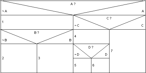
Example 4 The design of the decision symbol forces the programmer to recognize the significance of compounding IF-THEN-ELSE statements. In this example (figure 10) the logical conditions that hold for each of the seven process symbols is visually determined:
Not only does this notation help the programmer to think in an orderly manner, it forces him or her to do so.

Figure 10
The absence of any representation of the GOTO or branch statement requires the programmer to work without it: a task which becomes increasingly easy with practice. Programmers who first learn to design programs with these symbols never develop the bad habits which other flowchart notation systems permit. The development of programs with these symbols forces a structured program and helps prevent the programmer from developing a poorly organized program.
Since no more than fifteen or twenty symbols can be drawn on a single sheet of paper, the programmer must modularize his program into meaningful sections. The temptation to use off-page connectors, which lead only to confusion, is eliminated. Finally, the ease with which a structured flowchart can be translated into a structured program is pleasantly surprising.
We believe that the control structures described above are sufficient to get the flavor of the model. However, there are no strict rules regarding their use. What we have described is for the most part language independent. But in order to make the transition from flowchart to computer program more efficient, we need to express more powerful language constructs in our model.
BLISS (2, 6) and BCPL (7) are two languages for systems implementation. There is no GOTO statement in BLISS and its use in BCPL is discouraged. To compensate the desire for some kind of limited forward transfer, BLISS uses a construct whose scope is limited, name the EXIT construct (e.g. EXITBLOCK, EXITLOOP, etc.). BCPL uses the BREAK statement to terminate the smallest textually enclosing iteration, and the LOOP statement to transfer control to the point just before the test (and possible increment if it is an incremental iteration) in an iteration. To use specific language constructs like these, one might write:

Figure 11
since a BREAK statement only makes sense in a conditional.
BCPL is rich in convenient control and iteration structures and provides for loop testing at the top (FOR, WHILE, and UNTIL), at the bottom (REPEATWHILE, REPEATUNTIL) and at arbitrary points within the iteration (the REPEAT and BREAK combination). The first construct was given earlier:

Figure 12
The second, as one might guess is:

Figure 13
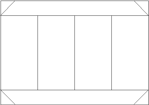
The third is not so natural:

Figure 14
Parallel processing can be represented by:

Figure 15
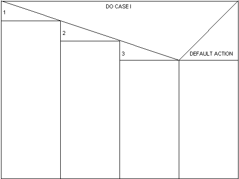
The CASE statement can be represented as:

Figure 16
The point is that the model is sufficiently powerful to allow the programmer to build his own structure as he identifies patterns of other structures, or as the need arises.
Although we have not made the programmer?s job any easier, and in fact more forethought may be required, we believe the benefits in debugging, self-documentation, and maintenance greatly outweigh the additional cost.
Further explorations are revolving about the context-free nature of this language. We also note that while the Contour Model nicely describes ALGOL execution, it is even a nicer description of the execution of programs written from structured flowcharts (8).
REFERENCES
1. Top-Down Programming in Large Systems by H. Mills
Debugging Techniques in Large Systems (Courant Institute)
2. Reflections on a Systems programming Language by Wulf et al
SIGPLAN Notices V 6 No. 9
3. Structured Programming by E. W. Dijkstra
NATO Science Committee - Software Engineering Techniques
April 1970
4. GO TO Statement Considered Harmful by E. W. Dijkstra
CACM V 11 No. 3
5. Flow Diagrams, Turing Machines and Languages With Only Two Formation Rules by C. Bolm and G. Jacopini
CACM V 9 No. 5
6. BLISS Reference Manual by Wulf et al
Carnegie-Mellon Technical Report
7. BCPL Reference Manual by M. Richards
8. The Contour Model of Block Structured Processes by John B. Johnston
SIGPLAN Notices V 6 No. 2